Carbonation sounds like an abstraction until you learn that it silently disarms the one system protecting embedded steel. It is slow, invisible, and almost entirely determined by concrete quality and cover depth, which makes it one of the most predictable durability problems in the built environment.
The chemistry, minus the chemistry
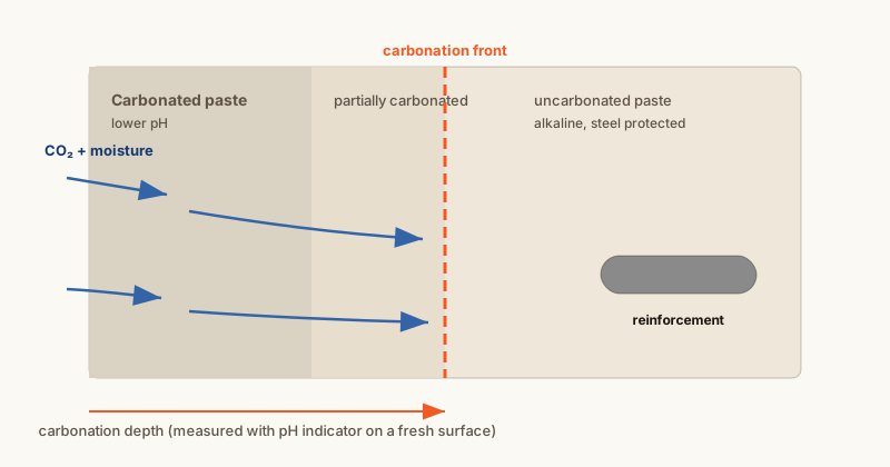
Fresh cement paste is strongly alkaline. Carbon dioxide from the air, dissolved in the pore moisture, reacts with alkaline compounds in the paste (chiefly calcium hydroxide) and converts them to calcium carbonate. The reaction consumes the paste's alkalinity.
The reaction proceeds from exposed surfaces inward, as a moving boundary: the carbonation front. Behind the front, the paste is carbonated and its pH has dropped; ahead of it, the paste retains its original alkalinity.
Why the front matters: the steel's protection
The embedded steel's passive film exists because the surrounding concrete is alkaline. When the carbonation front reaches the depth of the reinforcement, the environment at the bar surface is no longer alkaline enough to maintain that film, and corrosion becomes possible across the whole bar surface, not just at localized spots as with chlorides.
Three parameters control when this happens:
- Cover depth. The front has to travel the full cover distance. More cover means more years.
- Concrete quality. Dense, low-permeability paste slows CO2 diffusion substantially.
- Moisture condition. Carbonation needs moisture to dissolve CO2 but needs air-filled pores to move inward. Concrete in the intermediate humidity range carbonates fastest; fully saturated concrete carbonates slowly (CO2 diffuses poorly through water-filled pores), and bone-dry concrete also reacts slowly.
Carbonation versus chloride attack
The two depassivation mechanisms are often mentioned together but behave differently:
- Geometry. Chloride attack tends to initiate locally where chloride concentration first exceeds threshold; carbonation advances as a front and depassivates along the whole bar once reached.
- Source. Chlorides come from the environment (salt, sea); carbonation comes from the atmosphere itself, needing no salt at all.
- Rate. Chloride ingress can be fast under heavy salt loading; carbonation is slow, typically millimetres per year or less in decent concrete, faster in porous or poorly cured concrete.
- Testing. Both are straightforward to measure: carbonation depth with a pH indicator sprayed on a freshly broken surface; chlorides by profile testing (see our chloride article).
A given structure can be at risk from one, both, or neither, which is why condition assessment distinguishes them rather than assuming.
Why older and thinner elements matter
Carbonation depth grows roughly with the square root of time (a classic diffusion-controlled process). That has visible consequences:
- A 40-year-old building's carbonation depth may now be approaching the bar depth where a 20-year-old one is nowhere close.
- Thin or lightly covered elements (parapets, thin facades, stair nosings) reach their reinforcement much sooner than thick slabs.
- Poorly cured or high-w/cm paste carbonates faster than dense paste of the same age.
What it looks like in the field
Carbonation-driven corrosion tends to produce widespread, uniform rust staining and spalling along bars, in structures without heavy salt exposure: parking garages in mild climates, older buildings with shallow cover, and elements exposed to weather but not salt. Where staining appears without a salt source, carbonation is a natural first suspect, confirmable with a pH spray test on a freshly broken or drilled surface.
What the field test looks like
Carbonation depth is among the easiest durability measurements to take:
- A fresh surface is exposed, by breaking a corner, drilling, or coring, so that unweathered interior paste is visible.
- A pH indicator solution (phenolphthalein is the standard choice) is sprayed on the fresh surface.
- The indicator turns purple/pink where the paste is still alkaline and stays colourless where it is carbonated. The boundary between them is the carbonation front.
The measurement is the distance from the exposed face to that colour boundary, in millimetres. Comparing that depth to the cover depth (measured with a covermeter) answers the practical question: how far is the front from the steel, and, with repeated measurements over years, how fast is it moving?
The test costs little, which is why it belongs in condition assessments wherever corrosion is suspected in structures without heavy salt exposure. It is also a useful check on the chloride hypothesis: a structure with deep carbonation and low chlorides tells a different story from the reverse, and the remedies differ.
Which structures should care most
The carbonation conversation is most relevant for:
- Older structures with shallow cover: parapets, facade elements, stair elements, thin canopies.
- Buildings and structures without significant salt exposure, where corrosion is suspected: carbonation is the default suspect when staining appears without a salt source.
- Concrete that was poorly cured or made with high-w/cm paste, which carbonates faster than dense paste of the same age.
- Indoor structures with moderate humidity, the moisture band where carbonation moves fastest; fully saturated or bone-dry concrete carbonates slowly.
Where chloride exposure dominates (parking structures, marine elements, salted road structures), chloride testing takes priority and carbonation testing supplements it. Both pathways can be present on the same structure in different areas.
The time math, in one table
Carbonation depth grows roughly with the square root of time (classic diffusion behaviour), which means the rate slows as the front moves inward. The practical implications, using the square-root relationship as the frame (actual rates depend on the concrete):
- Doubling the cover more than doubles the time to reach the steel (four times the time, roughly, for the same rate constant).
- A carbonation rate that reaches a 20 mm cover in 30 years would take far longer to reach a 40 mm cover.
- Remedial work that adds dense cover material (or slows diffusion) buys disproportionate time for exactly this reason.
This is why cover depth appears in durability codes as a first-order parameter, and why "how much cover is over this steel?" is one of the most cost-effective questions in any corrosion assessment.
What this article does not tell you
It does not rate any specific structure, and it does not quantify carbonation rates for any mix; those depend on materials, curing, and exposure, and are established by testing. It also does not evaluate repair products or coatings.
Where to go next
Why Reinforcement Corrodes Inside Concrete covers the corrosion process both mechanisms share, and What a Petrographic Examination Can Reveal shows how paste condition is examined directly. For the salt-driven counterpart, read Chloride Ingress and Reinforced Concrete.